Table of Contents
Gears are the backbone of machinery that plays a pivotal role in mechanical devices and systems. These intricate components dictate motion and transmit torque between machine parts, ensuring everything runs smoothly. But, much like any other technical domain, the world of gears is vast, filled with different types, each serving a unique purpose.
This article examines the various types of gear, their classifications, and more.
Understand the Gears and its Mechanism
The essence of mechanics and motion is embodied within the structure of gears. As a pivotal component in machinery, gears not only dictate the movement of devices but define their efficiency, power, and precision. Let’s delve deeper into understanding gears.
Gears are rotating machine elements that transmit torque through the engagement of teeth. Their primary function is to change the speed, torque, or direction of mechanical energy. Here’s a simplified breakdown:
- Functionality: Gears work on the basic principle of leveraging mechanical advantage. Two gears interacting with each other will either increase or decrease power, based on their sizes.
- Tooth Engagement: The teeth of one gear mesh with the teeth of another, ensuring consistent motion without slippage.
- Transmission: Through this interaction, gears can transmit motion and force to other components or gears.
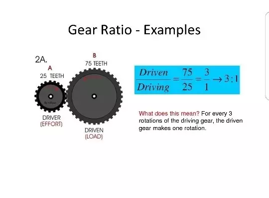
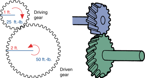
If we talk about the mechanism, every gear operates through a set mechanism that ensures its functionality. This mechanism often involves “drive gear and driven gear”. The drive gear is the gear that receives power directly from the power source and initiates movement. While the driven gear receives motion and torque from the drive gear. The combination of these gears defines the overall output and efficiency of the mechanical system.
Key Parameters Defining Gears
For a more in-depth understanding, it’s essential to familiarize oneself with the vital parameters associated with gears. The following table quickly outlines the key gear parameters.
Table: Quick Overview of Gear Parameters
| Parameter | Definition |
|---|---|
| Gear Ratio | Ratio of teeth between driven and drive gear |
| Gear Torque | Turning force exerted by a gear |
| Gear Speed | Rate at which a gear rotates |
| Pitch Circle | Theoretical circle for gear dimension calculation |
| Module | Ratio between pitch diameter and number of teeth |
| Backlash | Clearance between teeth of meshing gears |
| Addendum | Height of the gear tooth above pitch circle |
| Dedendum | Depth of the gear tooth below pitch circle |
Classifications of Gears on Different Basis
Gears, pivotal to countless mechanical applications, manifest in a broad spectrum of designs and specifications, tailored to individual operational demands. Gears are classified into three main bases, axis of rotation, tooth configuration, and shape.
Based on the Axis of Rotation
The axis of rotation pertains to the orientation and relationship of the rotational axes between two meshing gears. Different types of gears are used depending on how the axes of the two gears are oriented relative to each other.
Examples
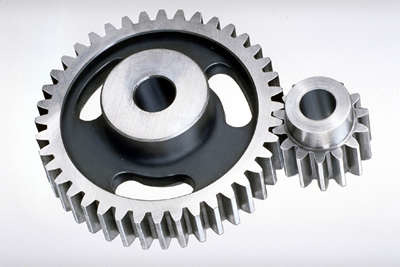
1. Parallel Axes: Spur Gear is the most common type of gear, it has straight teeth that run parallel to the axis of rotation. They transmit motion between parallel shafts.
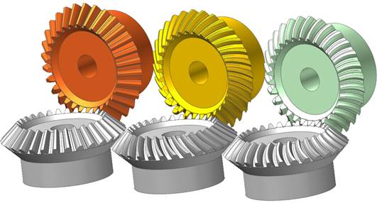
2. Intersecting Axes: Bevel gears have teeth that are cut on a bevel, and they transmit power between shafts that intersect at an angle, typically 90 degrees. They’re often found in devices like hand drills.
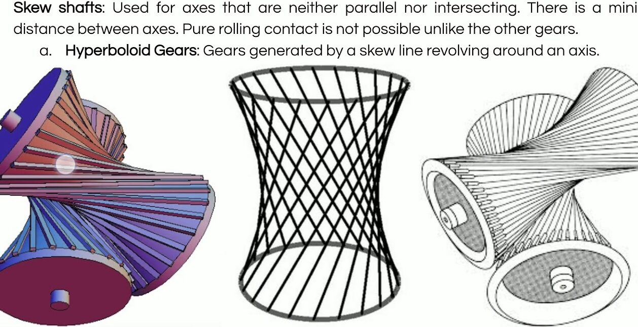
3. Skew Axes (non-intersecting and non-parallel): Helical gears have teeth that are cut at an angle to the face of the gear. They are used to transmit power between parallel or slightly skewed axes. Their angled teeth produce smoother and quieter gear operation compared to spur gears.
Based on the Tooth Configuration
Tooth configuration deals with the shape and design of the individual teeth on the gear. The tooth profile affects the efficiency, strength, and noise level of gear operation.
Examples
- Straight Teeth: As mentioned before, spur gears have straight teeth. These teeth produce sudden and direct contact, which makes these gears noisy at high speeds.
- Curved Teeth: Herringbone Gear involves teeth that are shaped like the letter “V”. The dual-angled design allows for smoother gear operation, often with little to no axial thrust due to the opposite angles balancing out.
Based on the Gear Shape
The overall shape or form of the gear also serves as a classification criterion. This can dictate how the gear fits into machinery or how it interacts with other gears.
Examples
- Circular: Most gears are circular, allowing for smooth, continuous transmission of power as the teeth mesh in succession.
- Non-Circular: Cam Gear gears are intentionally designed not to be round. They’re used in situations where the speed or direction of rotation needs to change based on the gear’s shape. For instance, in some engines, cam gears are used to open and close valves at specific intervals.
- Rack (Linear): A rack is a straight, flat gear that meshes with a round pinion gear. When the pinion turns, it moves along the rack in a straight line. This mechanism is commonly used in car steering systems, where turning the steering wheel (pinion) moves the steering rack to turn the wheels.
What Are the Common Types of Gears?
Gears hold a pivotal position, transmitting motion and force seamlessly. To appreciate the intricate mechanics and applications, it’s crucial to identify and understand various gear types.
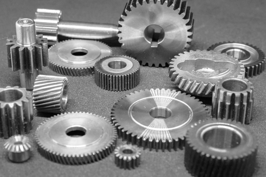
- Spur Gears
These are the most common type of gears, easily recognizable by their cylindrical shape with straight teeth that are parallel to the axis. When in motion, they produce a characteristic noise due to the sudden contact of their teeth. Often used in clocks, washing machines, and blenders, they serve where noise control isn’t critical.
- Helical Gears
Characterized by teeth that are cut at an angle to the gear’s face, helical gears operate with more refinement than spur gears. Their angled teeth engage gradually, ensuring a smoother, quieter operation. Due to their design, they are commonly found in heavy-duty applications like automobiles.
- Bevel Gears
Primarily used to change the direction of shaft’s rotation, bevel gears have conical shapes. Their teeth can be straight, spiral, or hypoid. Standard applications include hand drills and differential drives of vehicles.
- Worm Gears
Resembling screws, worm gears mate with a worm wheel, reducing rotational speed or allowing higher torque multiplication. They are adept at large gear reductions, often seen in conveyors and elevator systems.
- Rack and Pinion Gears
A unique pairing, where the pinion (a circular gear) meshes with a flat-toothed rack. Transforming rotary motion into linear motion, these are primarily found in steering systems of cars and trains.
- Planetary Gears
Comprising a central sun gear surrounded by planet gears, which in turn mesh with an outer ring, planetary gears can achieve high torque in compact spaces. They’re integral to automatic transmissions in vehicles.
- Herringbone Gears
Recognizable by their distinctive V-shaped teeth, these gears combine two helical gears set in opposite directions. This design eliminates axial thrust, ensuring efficient, smooth operation, and they’re primarily used in heavy machinery.
- Crown Gears
With teeth projecting at right angles to the plane of the wheel, crown gears are a form of bevel gear. They interact with other gears on parallel axes, often used in differential drives.
- Internal Gears
Contrary to typical gears where teeth are on the outside, internal gears have teeth on their inner surface. They mesh with external gears and are frequently utilized in planetary gear systems.
- Face Gears
These gears transmit power between intersecting shafts. The teeth are cut on the face of the gear and are aligned radially, resembling spur gear teeth. Applications are somewhat limited, often found in right-angle drives.
- Non-circular Gears
Stepping away from the traditional, these gears don’t have a circular shape. Instead, they’re designed for specific tasks and often appear in textile machinery and car windshield wipers.
- Sprocket Gears
Not quite the conventional gear, sprockets interact with chains in machinery. Their teeth prevent the chain from slipping, ensuring smooth operations. They’re vital in bicycles, motorcycles, and conveyor systems.
Table: Quick Reference to Gear Types
| Gear Type | Characteristic Feature | Common Applications |
|---|---|---|
| Spur | Straight, parallel teeth | Clocks, blenders |
| Helical | Angled teeth | Automobiles, heavy machinery |
| Bevel | Conical shape, variable teeth designs | Hand drills, vehicles |
| Worm | Screw-like design | Conveyors, elevators |
| Rack and Pinion | Pinion with a flat-toothed rack | Car steering systems |
| Planetary | Central sun gear with surrounding planets | Automatic transmissions |
| Herringbone | V-shaped teeth | Heavy machinery |
| Crown | Teeth at right angles to the wheel’s plane | Differential drives |
| Internal | Teeth on the inner surface | Planetary gear systems |
| Face | Radially aligned teeth on gear’s face | Right-angle drives |
| Non-circular | Non-standard, varying shapes | Textile machinery, windshield wipers |
| Sprocket | Teeth designed to engage with chains | Bicycles, conveyor systems |
Gear Manufacturing at Its Finest
In the realm of machinery and equipment, the importance of gears cannot be understated. Their pivotal role in transmitting motion and generating mechanical advantage makes them integral to a vast array of applications, from simple clock mechanisms to intricate automobile transmissions. The process of manufacturing these essential components has witnessed profound evolution over the years, with modern techniques promising unprecedented precision and efficiency.
Traditional vs. Modern Methods
The journey of gear manufacturing has traversed from manual craftsmanship to sophisticated automation.
Table: Traditional Vs Marden methods
| Category | Method | Description |
|---|---|---|
| Traditional Methods | Manual Machining | Artisans manually operated lathes and milling machines. They crafted each gear based on skill and intuition. This method was time-consuming and lacked consistency compared to modern machinery. |
| Forging and Casting | This process involves heating metal until it becomes malleable and then molding it into the desired gear shape. Gears produced this way often required additional refining and finishing to meet exact specifications. | |
| Hobbing | A traditional and still widely used method, hobbing involves using a hob (a special type of milling cutter) to cut the gear’s teeth. The gear blank and the hob rotate simultaneously, ensuring the correct profile of the teeth. | |
| Modern Methods | CNC Machining | This method revolutionized gear manufacturing. CNC machines, controlled by computerized systems, ensure that every gear produced meets exact specifications. They offer high precision, consistency, and speed. |
| Electrical Discharge Machining (EDM) | By using controlled electrical sparks, EDM can shape hard metals into intricate gear profiles. It’s especially beneficial for manufacturing custom gears for specific applications. | |
| Laser Cutting | A non-contact process, laser cutting uses high-intensity laser beams to cut and shape metals. It’s highly precise, ensuring smooth edges and accurate profiles. | |
| 3D Printing | Emerging as a promising technology, 3D printing or additive manufacturing builds gears layer by layer, allowing for unique designs and rapid prototyping. |
Unity manufacturer’s Expertise in Gear Manufacturing
In the intricate landscape of gear manufacturing, Unity stands out as a beacon of excellence. Their commitment to quality, innovation, and precision has established them as leaders in the industry.
- State-of-the-Art Facilities: Unity boasts advanced manufacturing plants equipped with the latest CNC machines, laser cutters, and EDM equipment. Their adoption of cutting-edge technology ensures products of the highest quality and precision.
- Experienced Craftsmanship: Blending modern techniques with traditional craftsmanship, our team of engineers and technicians possess the expertise to handle a wide range of gear manufacturing projects. Their deep understanding of gear mechanics and design intricacies ensures optimal performance and durability.
- Custom Solutions: Recognizing that each application has its unique requirements, Unity specializes in custom gear solutions. Whether it’s a bespoke design or a specific material, they have the capability to tailor-make gears that perfectly fit the client’s specifications.
- Quality Assurance: Every gear that exits our facilities undergoes rigorous quality checks. Using advanced metrology equipment, they ensure that each gear adheres to the promised specifications and performance metrics.
- Sustainability: Unity isn’t just committed to manufacturing excellence but also to sustainable practices. Their eco-friendly methods and dedication to waste reduction highlight their responsibility towards the environment.
- End-to-End Services: From conceptualization and design to production and post-production checks, Unity offers comprehensive gear manufacturing solutions. Their holistic approach ensures that clients receive products that exceed expectations.
Material Options for Gears and How to Choose the Right One?
Gears, the silent workhorses of machinery, play a pivotal role in transmitting motion and force across myriad applications. As their importance becomes evident in the smooth functioning of systems, the material used to craft these components takes center stage. The durability, efficiency, and overall lifespan of gears hinge heavily on their constituent materials.
What Are the Material Options?
Materials for gears aren’t chosen at random. Instead, they are meticulously selected based on the specific requirements of the application. Here’s an exploration of popular gear materials:
Table: Materials for gear manufacturing
| Gear Material | Description |
|---|---|
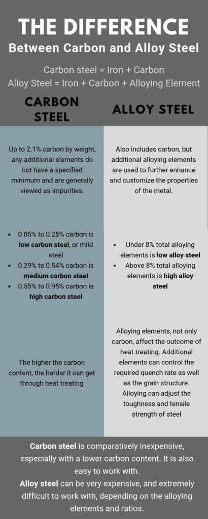
| Steel Gears | The most common choice for industrial applications, offering high strength and durability. Varieties include alloy steels, carbon steels, and stainless steels. Stainless steel gears resist corrosion, making them ideal for moisture-exposed applications. |
| Cast Iron | Known for its excellent vibration-damping capabilities and wear resistance. However, it’s brittle and might not be ideal for high-impact applications. |
| Brass and Bronze | Non-ferrous metals are often used for worm gears. They offer good sliding properties, resist wear, and possess natural anti-galling properties, ensuring longevity in sliding motion applications. |
| Plastics | Gained traction due to the rise of lightweight and efficient machines. Materials include nylon, polycarbonate, and acetal. They are corrosion-resistant, quiet in operation, and ideal where lubrication is challenging. |
| Aluminum | Predominantly used in automotive applications. These gears are lightweight with a decent strength-to-weight ratio and offer good thermal conductivity, ensuring heat dissipation during operations. |
| Composite Materials | Emerging technology combines the benefits of two or more materials. These offer reduced weight, tailored thermal expansion properties, and improved noise and vibration characteristics. |
Choosing the right gear material isn’t mere guesswork; it’s an informed decision based on several parameters:
- Operational Load: Gears subjected to heavy loads require materials with high tensile strength, like steel. For lighter loads, materials like plastic or aluminum might suffice.
- Environmental Conditions: In corrosive environments, materials like stainless steel or plastic that resist rust and degradation are preferred.
- Speed and Temperature: If a gear system is expected to run at high speeds or under elevated temperatures, the material should have good thermal conductivity and resistance to thermal expansion. Steel and aluminum are solid contenders here.
- Noise Considerations: For machinery where noise reduction is critical, like in medical devices, softer materials or those with inherent damping properties, such as plastics or cast iron, are chosen.
- Lubrication: If lubrication is sporadic or challenging, materials with innate self-lubricating properties, like certain plastics or brass, can be beneficial.
- Cost-effectiveness: While it’s crucial to select a material based on functional requirements, budget constraints often play a role. Materials like steel and cast iron tend to be more economical than specialized plastics or composite materials.
- Manufacturability: Some materials are easier to mold, cast, or machine than others. If rapid production is a requirement, opting for materials that lend themselves to quick manufacturing processes is a wise move.
- Weight Constraints: For applications like aerospace or certain automotive parts, where weight plays a critical role in efficiency, lightweight materials like aluminum or specific plastics are preferred.
- Lifecycle Expectancy: If a gear’s expected life is short, as in some disposable products, cheaper materials might be chosen. For long-term applications, investing in robust materials like steel or bronze is more viable.
Summing Up
Gears are mere cogs in a machine. Different types of gears in machinery and hardware hold the profound responsibility of orchestrating motion and power in countless mechanisms. From understanding their foundational principles to exploring gear types, and the manufacturing intricacies, our exploration highlights the depth of gears. The choices in material selection underline the need for balance between durability, efficiency, and application specificity.
If you are looking for any related services, Unity Manufacture is a committed manufacturer of gear and related accessories. We produce precise and high-quality gears with modern manufacturing approaches.
FAQs
How are gears classified with their applications?
Gears are classified based on their design, axis of rotation, teeth orientation, and application, such as automotive, aerospace, or machinery.
What is a gear ratio?
It denotes the relationship between the turning speeds of two interconnected gears.
How does gear torque affect machinery?
Gear torque relates to its power and force, impacting the machinery’s overall performance and efficiency.
Why are different types of gears used in machinery?
Each gear type serves a unique purpose, ensuring optimal performance and efficiency in specific applications.
What’s the difference between gear types based on teeth orientation?
The orientation, like straight, helical, or spur, affects the gear’s operational smoothness and noise level.
Why choose Unity Manufacture for gear manufacturing?
With state-of-the-art techniques and extensive expertise, Unity offers unmatched precision and quality in gear manufacturing.
Request a quote today!
[contact-form-7 id="1578" title="Contact form"]
Please compress the file into a ZIP or RAR file before uploading. Alternatively, send through your RFQ by email.
enquires@unitymanufacture.com

